kair.us/ projects/ jakadapter/

Dual Atari joystick adapter v2
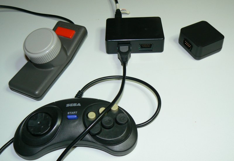
The Jakadapter allows connecting two Atari-style controllers to USB.
It supports standard joysticks, paddles and also Sega Megadrive
gamepads on both ports. It has cheap and simple hardware which is
easy to build yourself.
Features
- Supports two Atari / C64 / Amiga etc. digital joysticks
simultaneously
- Full-speed USB with up to 1000 Hz update speed (*)
- Supports paddles on both ports
- Supports SMS, Megadrive 3- and 6-button gamepads on both ports
- Works in Windows, Linux, Mac (standard HID game controller, no
drivers needed)
- Works in all major emulators (VICE, CCS64, WinUEA, Stella to
name a few)
- Upgradeable FW (Microchip compatible HID bootloader)
- Detects controller type automatically, no need to change
firmware
(*) Seems to depend on OS. Windows polls at 1000 Hz, Linux and OSX
poll at 500 Hz.
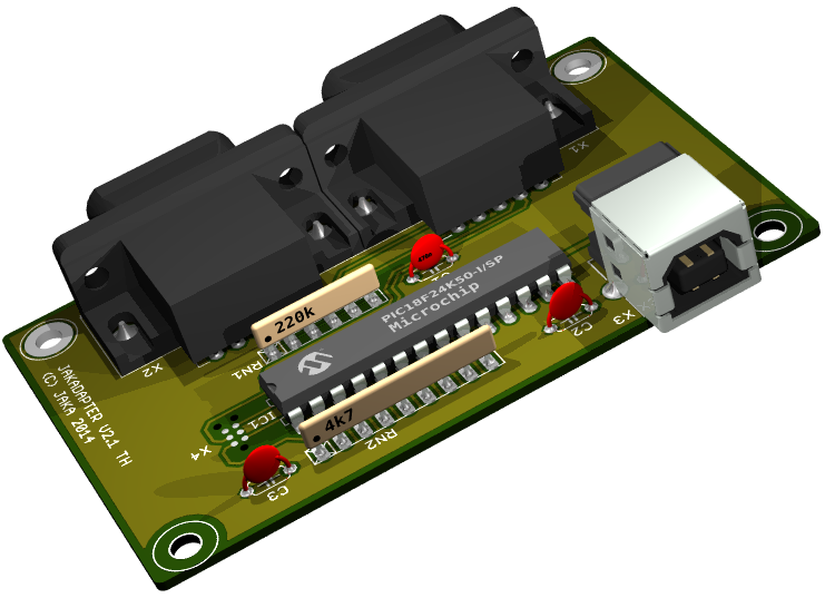
Hardware
The adapter hardware is based on PIC18F24K50, fairly cheap PIC with
integrated full-speed USB. The circuit is kept as simple as
possible, while trying to provide optimum performance. The schematic
is available in PDF below.
Circuit diagram v2.2
The PIC has integrated pull-up resistors at port B. There is also
internal pull-up at port E (only one pin available, RE3). I first
tried to use that also, but failed miserably. Reason is that even
/MCLR is disabled, bringing that pin higher than +5V causes entering
programming mode and causing reset of the PIC. So when connecting a
joystick to adapter, static charge at the joystick cable could
sometimes cause the PIC to reset, causing USB re-initialization.
Unlike other pins, /MCLR doesn't have ESD clamp diode to VCC. This
is the reason I had to make PCB re-spin from 2.0 to 2.1. Lesson
learned. I added external pull resistor from /MCLR to VCC and even a
small capacitor to protect capacitive coupling, probably a bit
overkill.
Ports A and C require external pull-ups. The external pull-ups are
chosen to match real C64 joystick ports. External pull-ups are used
on pin 6 (the fire button) on both ports. This ensures that
auto-fire works correctly on all joysticks. Some auto-fire circuits
are powered from the port pull-up, and not from the +5V line.
Since there were pins available, I use two pins per port to supply
+5V. This allows supplying up to 50 mA per port or alternatively
using one pin to supply current and other as A/D input to check if
there is too much current drawn, causing voltage to drop. There are
still three pins available. These could be used e.g. to drive two
bi-color LEDs to indicate the operation mode of each port. Another
possibility would be to have also pin 8 configurable for those odd
controllers which doesn't have pin 8 as ground.
I have aimed to use full speed USB which generally requires hardware
USB support from µC. There are SW USB implementations for Atmel µC's
that don't have any USB HW. I find these implementations quite
impressive. These are however currently limited to low speed USB.
Low speed USB supports maximum update rate of 100 Hz. In practice
that would perhaps not matter much, most HID devices are low speed.
And the games usually read the joystick input at 25 Hz or slower.
But I wanted to get the lowest possible lag.
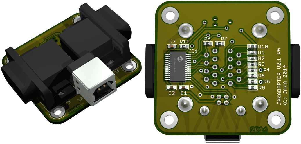
Layout
There are two versions of the layout:
The PCBs for are designed with Eagle.
Below Eagle 3D rendered through-hole
version board
And here's the SMD version, also rendered with Eagle 3D.
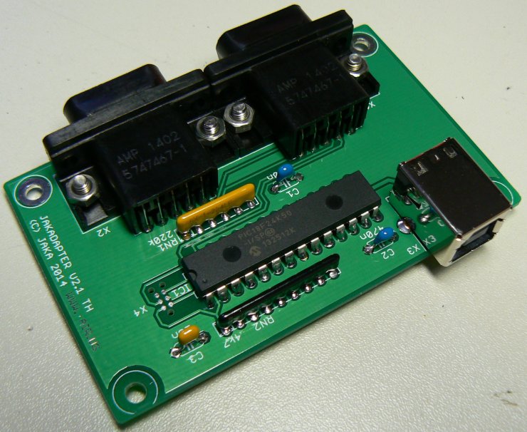
Finally, here's photo of actual through-hole version board.
And here are schematic and board files available for download:
jakadapter 2.2 through hole Eagle
.sch and .brd, Gerber
files, PCB
order from PCBWay, invite
link for PCBWay registration for some free credit and
bill of materials
including part numbers for Digi-Key and Mouser
jakadapter
2.1 SMD Eagle .sch and .brd
Firmware
Currently the FW size is about 7 kB. With the bootloader taking 2
kB, there is still 7 kB left for new features. The source code and
compiled .HEX file are available for download below. Note! USB
header file for HID descriptors is not included in the package, as
it is modified from CCS copyrighted code. Contact me if you have the
compiler and need the file.
jakadapter_21_v13.zip (Version
1.3, Aug 4, 2017. Improved paddle filter algorithm. Bootloader
embedded to .hex file. Compiled with CCS compiler v5.054)
jakadapter_21_paddlemouse_v11.zip
(Version 1.1, Aug 5, 2017. This is experimental version which is
acts as a HID mouse and not joystick. This allows to use paddles in
VICE emulator. Use
paddles in port 1 of Jakadapter. You might want to turn off mouse
acceleration from operating system (this is called 'Enhance pointer
precision' in Windows)
Starting from version 1.3, the bootloader
is already included in the jakadapter_21_vxx.hex file. To enter
bootloader mode, keep joystick 1 fire button pressed when connecting
USB cable.
Main updates since v0.5 which was used in original version of
adapter are:
- Support for paddles and Megadrive controllers also on port 2
- Added anti-jitter filtering to paddle readout. Now paddles
give very stable but quick readings.
- Reduced Megadrive 6-button controller button polling to 333 Hz
as some controllers were giving problems with 1000 Hz.
Directional pad and B & C buttons are still polled at 1000
Hz
- Added text 'Stelladaptor' to USB description so that Stella emulator uses
paddles correctly
- Megadrive controllers are recognized during USB enumeration
(plugging USB cable in). Standard joystick and paddles are
automatically recognized without re-plugging USB.
- Support for bootloader
How to build it
For a DIY build, it is easier to build the through-hole component
version. This chapter describes the steps required to build it. It
assumes you have basic electronics tools and know how to use them.
Order the parts
Order the parts which are listed in the BOM. To make it easier, I
have gathered a Digikey
shared cart and a Mouser
shared cart which have all the required components except
the PCB.
Order the PCB
You can order a batch of 10 boards for $5 + shipping (approx. $13
total) from PCBWay using this
link. If you haven't yet registered to
PCBWay, you can register
via this link and get some free initial credit (and also
earn me some credit as well). Or use the Gerber package and order
boards from your favorite manufacturer. Remember that board
thickness should be 1.2 mm to fit to enclosure.
Get a PIC programmer
If you don't have a PIC programmer or don't have a place/friend
where it could be programmed, the cheapest option is to buy a
PICkit2 or PICkit3. Also the cheap Chinese clones e.g. from eBay
will usually work.
Solder the components
Assembling the PCB is very straightforward job. Component
locations are marked on silkscreen, but you can also use this assembly drawing to find
which part goes where. Components IC1, RN1 and RN2 need to be
mounted with correct orientation. Pin 1 is marked with a dot or
notch, they have to match the assembly drawing. It is advised to
mount the d-sub connectors first with screws to the PCB and then
solder the pins. You can use 8 mm long M3 screws and M3 nuts. The
BOM and shared carts specify #4-40 3/8" imperial screws because
those are better available in Digikey and Mouser.
Program the PIC
Download the latest firmware.
Information on how to program the PIC, see here.
Cut holes to the enclosure
This is maybe the trickiest part in building the Jakadapter. A
proxxon or dremel is handy, but a fretsaw or knife will work too.
The PCB will be trapped between the enclosure and its cover. I
don't have any drawing or template for this, it is best to cut a
little at a time and do frequent trial fittings.
How to use it
There isn't much to instruct here. The Jakadapter will be
recognized as two HID compatible game controllers and doesn't
require any drivers. You just need to select the Jakadapter from
your emulator to be used as controller. You don't need to do any
calibration as was required with old analog PC joysticks. It
really is plug-and-play.
Testing the operation
To test operation of Jakadapter and also operation of your maybe
30+ years old joystick, you can use the tools provided by
operating system.
On modern Windows versions, the joystick calibration application
can't be found from the control panel anymore. But it still is
there, you can run it by pressing Win+R and type joy.cpl and hit
enter. Or on Windows 10 just open the start menu and type joy.cpl.
Unfortunately Windows can't read the USB descriptors properly and
it will display both ports of Jakadapter with same description.
Microsoft hasn't bothered to fix this even though the bug has been
there at least from Windows 2000.
On Linux systems you can use e.g. jstest command line tool.
Updating the firmware
The Jakadapter uses a bootloader, so the PIC programmer is not
required for updates. You can enter the bootloader mode by keeping
joystick 1 fire button pressed down when connecting the USB cable.
You can then use the update tools suggested on the my USB HID bootloader page.
Using paddles in VICE
The VICE supports
paddle emulation only with mouse. In order to use Paddles in VICE
with Jakadapter, I've created a special firmware. In order for it
to work, the mouse acceleration needs to be completely switched
off. I have detailed the setup procedure in this
post on Lemon64 forum.
Other joystick adapters
Here are some other similar projects or products. A short summary of
supported controllers, update rate, used HW etc. is provided. I do
not guarantee that all information provided here is correct.
Stelladaptor
10ms polling, 1 joystick, paddles
2600-daptor
1ms polling, 1 joystick, paddles
http://home.comcast.net/~tjhafner/2600-daptor.jpg
http://www.atariage.com/forums/topic/181321-announcing-new-2600-controller-usb-adaptor/
Retrousb
Atari retro port
1 joystick, no paddles
Retrousb
Genesis retro port
1 Megadrive 3 or 6 button pad
Raphnet
1 joystick, SMS, Megadrive 3 and 6 button, multitap, 10 ms polling
(atmega8)
Hexagons/Retro-Donald
USB Joystick adapter
2 joysticks, 10 ms polling (Atmel ATtiny 2313)
Simon
Inns
Atari
joystick
USB
adapter
2 joysticks, no paddles. 1 ms polling, PIC2550
Simon
Inns C64 Vice front-end
2 joysticks, paddles, keyboard, 1ms polling, PIC4550
Retro Adapter
Supports a huge range of different controllers with adapters. 10 ms
polling (atmega168)
Retronic Design USB Joystick adapter
Supports 1 joystick, SMS controller, CD32 gamepad and Amiga mouse.
10 ms polling (atmega-8).
kair.us/ projects/ jakadapter/
page created 23.7.2014
last updated 12.3.2020 webmaster@kair.us